Abstract
The Steel Tank Institute (STI) performed testing to demonstrate the stiffening effects from the soil-structure interface with an underground storage tank. The test demonstrated the importance of the soil in calculating the resistance to buckling in a buried environment. Current third-party listing agencies do not take the stiffening effect of the soil support into consideration with standardized steel wall thickness calculations.
Performance characteristics of a tank are similar to pipelines, although the tank heads provide additional stiffness to the structure. As a result, atmospheric tank wall thicknesses are thinner than typical pressurized potable water pipelines. Tanks are normally buried 4’-5’ at petroleum service stations, however, sometime the tanks need to be buried deeper.
STI buried a 64-inch diameter by 24 foot long steel tank 7 foot below grade, compacting the angular gravel backfill during placement to grade. A camera was placed in the tank to record deformations during the actual test. The excavation was filled with water such that the bottom of the tank was subjected to 12 feet-4 inches of static water head pressure. A vacuum pump was connected to a tank riser and a vacuum was pulled. The intent was to pull the vacuum until the tank buckled.
A vacuum of 16.5 inches Hg was established and the pump was unable to pull additional vacuum. The backfill was removed and the tank examined and the video of the inside of the tank reviewed. The tank did not buckle. The shell did not deform. The heads experienced approximately 2 inches of permanent deformation.
Calculations indicate that the tank was subjected to a 15.0 psi total buckling load. Formulations suggest that the soil-structure would provide resistance to buckling up to 21.0 psi. Third party standard formulations that do not take the soil support into consideration suggest that the tank would buckle in a range from 1.3 psi to 6.0 psi.
The test clearly demonstrates the importance of the soil in calculating the resistance to buckling in a buried environment. The soil-structure interaction provides significant additional stiffness to the structure, whether the structure is a pipeline or a tank, as demonstrated in this test.
Introduction
The Steel Tank Institute (STI) and Steel Plate Fabricators Association (SPFA), merged in 2004 to form STI/SPFA, a trade association with two divisions. The Steel Tank Institute develops standards and performs research in the steel tank industry. In 2011, the STI performed an in-situ test to gather information about the strength of steel and its ability to resist deformation and buckling in a buried condition. This paper presents the results of this research effort. One of STI’s primary goals was to show that soil assists in supporting the steel buried tank, significantly increasing its resistance to buckling. But first, an introduction to typical construction and installation details of steel tanks is provided.
The Environmental Protection Agency regulates approximately 600,000 underground tanks storing hazardous liquids. Buried tanks are also used to store water and many other liquids. Most tanks are made from steel or fiberglass reinforced plastic (FRP). Underground tanks are subject to many of the same geotechnical forces as pipelines that can cause deformation, cracking, and buckling. Due to the potential liability with storage of hazardous liquids, tank manufactures and tank owners have no tolerance for leakage or failures.
Tanks are typically buried in granular soils such as sand or pea gravel. The majority of tanks are buried 3 feet – 7 feet below grade. Many tanks are buried underneath a concrete pad or asphalt pavement, as what one normally can observe at the neighborhood motor vehicle fueling service station. Loads imposed on the top of tank, such as live loads from trucks and dead loads from soil, are not a factor in design with typical tank installations due to the burial depth.
The primary difference between a tank and a pipeline is that a tank has a finite length and is fabricated with end caps called tank heads. The tank heads tend to stiffen the tank immediately around the ends of the tank shell, or cylinder. Typical storage tanks installed at gas stations today have capacities ranging from 10,000 gallons to 30,000 gallons. The largest buried tank has a capacity of 50,000 gallons, with dimensions of 12 feet in diameter by 60 feet in length. Hence, the mid-point of the shell of such a large storage tank will not experience the same stiffening effect of the tank head as do the ends of the shell. Thus, the mid-point of that tank more closely simulates conditions similar with a pipeline.
The length to diameter ratio of steel underground storage tanks can be as high as 8:1, although typically this ratio is 4:1 or 5:1. Typical fabrication specifications are spelled out in Underwriters Laboratories Standard UL 58, Steel Underground Tanks for Flammable and Combustible Liquids. Wall thicknesses are calculated using a classic formula from Roark’s Formula for Stress and Strain based on buckling loading.
External pressure and internal vacuum are the driving forces in making this calculation to prevent buckling. Consideration for strength provided by the soil is not included within the UL 58 standard. Specifically, the UL 58 Standard states:
The calculated pressure from the Roark equation shall be equal to or greater than the external pressure at the bottom of the tank surrounded by only water and submerged 5 feet (1.52 m) or at a depth equal to the manufacturer’s specified maximum burial depth, whichever is greater. The buckling pressure shall be calculated using the following equation:
P = [0.807 Es ts2/Lr] [(1 – n2)-3 (ts/r)2]0.25
in which:
P is buckling pressure (psi)
Es is modulus of elasticity of steel (29.5 x 10 psi for structural grade A36 carbon steel)
ts is thickness of steel tank shell (inches)
L is length of tank (inches)
r is radius of tank (inches), and
n is Poisson’s Ratio (0.287 for structural grade A36 carbon steel)
The goal of the STI research study was to show that soil assists in supporting steel tanks from buckling.
Research Study Goal
STI/SPFA had the following concerns that led to performing the actual physical test:
- Steel underground storage tank fabricators compete against non-metallic FRP tanks
- Underwriters Laboratories publishes separate standards for steel and FRP underground storage tanks (UST’s)
- UL 1316 is titled “Glass-Fiber-Reinforced Plastic Underground Storage Tanks for Petroleum Products, Alcohols, and Alcohol-Gasoline Mixtures” and includes the performance testing requirements for such tanks
- Steel tank industry wanted to test a steel tank to UL 1316 performance requirements since the UL 58 standard for steel tanks does not allow for a performance test that recognizes the stiffening effect of the soil surrounding the The UL 1316 standard for non-metallic tanks does allow for a performance test that recognizes the stiffening effect of the soil.
Case Study
Tank Background
The Acterra Group manufactured the tank in their Marion, Iowa facility in November 2010. The Acterra Group is a major manufacturer of underground and aboveground steel tanks for storage of fuels, chemicals, and dry solids. Acterra Group also distributes, installs and constructs petroleum equipment systems and provides consulting for all major renewable energy technologies. Following are details applicable to the test tank.
Tank Size: 4,000 Gallons
Construction: Single-wall, Bare Steel, Horizontal Underground Storage Tank
Tank Di meter: 64 in.
Tank Wall Thickness: 0.172 in. (measured) Tank Length: 24 ft.
Figure 1 depicts the cross-section of the test tank. Note that this tank has a 24 inch diameter manhole two feet from one end and that the tank ends consisted of flat plate heads the same thickness of the tank itself. The tank did not have any lining or coating or any internal or external stiffening elements.
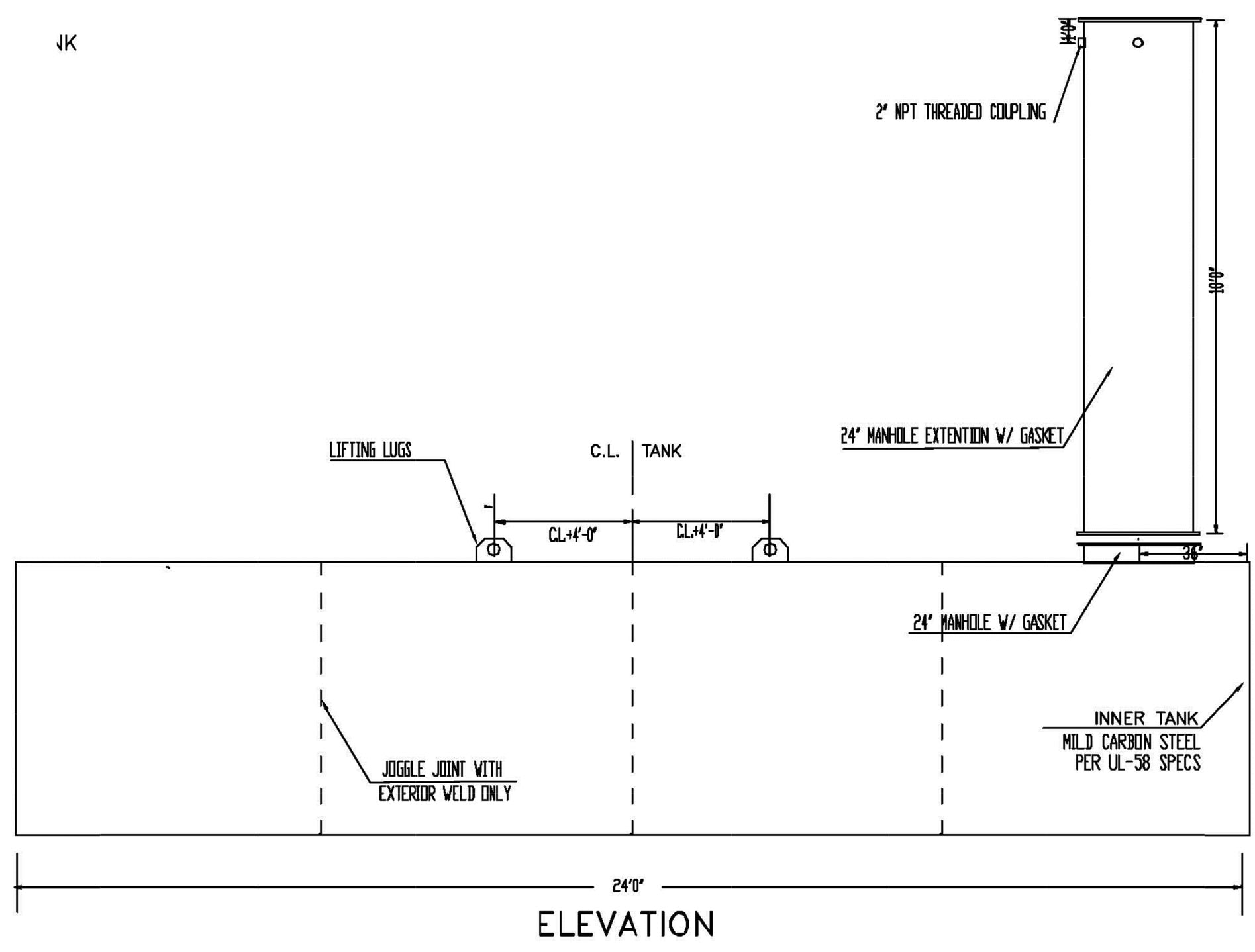
Figure 1 – Test Tank Detail (figure not to scale)
The purpose of the manhole was to provide access to the tank for inspection after burial and for camera placement prior to pulling the vacuum.
Initial Calculation
By utilizing the aforementioned Roark equation and substituting the actual test tank dimensions into the equation, an allowable buckling load of 6 psi is determined. This results in limiting the steel test tank burial depth to approximately 8 feet to the top of the tank.
FRP Underground Tank Discussion
UL has different requirements for the use of FRP underground storage tanks than what is required for steel tanks as shown below. UL 1316 contains strict performance testing requirements for FRP tanks with Sections 11 – 13 depicting three of the external load tests that the tank must undergo are as follows:
11 Water-Load Test
11.1 A tank shall be:
- Placed in a sand bed so that one-eighth of the tank diameter is buried, and
- Filled to capacity with water for 1 hour The tank shall not be damaged.
12 External Pressure Test
12.1 A tank shall be tested as described in 2 The tank shall not implode or otherwise be damaged.
12.2 The empty tank is to be installed in a test pit using the specified anchoring system and the specified backfill The pipe is then to be filled with water to such a level that the tank is submerged to its maximum specified burial depth. The tank is to remain submerged for 24 hours. While the tank is still submerged, it is to be subjected for 1 minute to a partial internal vacuum so that the internal pressure on the tank is 5.3 inches of mercury (17.9 kPa) less than the external pressure imposed by the hydrostatic head.
13 Internal Pressure Test
13.1 A tank shall withstand without rupture for 1 minute an internal pressure as specified in Table 13.1
Table 13.1
Internal pressure test
| Maximum diameter of tank feet (m) | Applied pressure, PSI (kPa) |
|---|---|
| 10 (3.0) or less | 25 (172) |
| More than 10 | 15 (103) |
STI/SPFA technical staff have asked UL engineers to clarify the above requirements in the past. Following are the answers supplied by UL:
- Water load test – fill tank to capacity with water for one hour. Tank is sitting in a sand bed up to 1/8 the diameter of the The tank must sit there for an hour and not leak.
- Using the same tank, still sitting in the sand bed, pressurize for one minute to 25 The tank cannot leak. The 25 psi pressure is used on tanks less than 10 foot diameter while 15 psi is used on tanks greater than 10 foot.
- Lastly, the External Pressure test is conducted on an empty tank placed in a pit & anchored as needed. The tank is then backfilled and the pit is filled with water to maximum burial depth (so as to have standing water on the surface). The tank is then left empty with no additional load placed on it for a 24 hour dwell time. Finally 5.3 inches Hg vacuum is pulled and held for one minute. Once again, the tank cannot leak.
Testing to meet Sections 11 and 13 was previously conducted in San Antonio. This research will only correlate to the requirements contained in Section 12, “External Load Test”. During the discussions with UL engineers, it was noted that FRP tanks have been tested at a 7 foot burial depth with claims of safety factors of 5:1. It was then decided to test a buried steel tank, embedded in a typical backfill material that is commonly utilized for steel tanks, to a depth of 7 feet.
Test Set-Up
The test tank was installed at the Acterra Group facility on May 24, 2011. The test tank installation was to model a typical steel tank installed per STI/SPFA installation requirements.
STI/SPFA installation guidelines STI R971 for Urethane Coated Steel Underground Storage Tanks, and all other STI UST installation instructions, contain the following general bedding and backfill requirements:
1.3 Bedding and backfill material shall consist of homogenous pea gravel, crushed stone, clean sand or natural earthen materials. Crushed stone, clean sand and natural earthen materials shall be capable of passing 100% through a 1/2 inch (13 mm) sieve and no more than 12% by dry weight through a #200 sieve (0.0029 inch (0.0754 mm)). Pea gravel shall be no larger than 3/4-inch (19 mm). The materials shall be free of all foreign materials, such as but not limited to, bricks, metals, concrete and plastics.
1.4 The backfill material may be from the tank site if it meets this description, or it may be delivered to the site from another source.
1.5 Sand or natural earthen materials used as backfill shall be placed into the excavation in 12-18 inch (305-458 mm) vertical lifts, compacted after each lift, at least 60% up the vertical height of the tank.
The actual material used was a well graded crushed stone. Braun Intertec of Cedar Rapids, Iowa supplied a soils technician to oversee the bedding and backfill placement along with measuring the density of the compacted material in each lift. As the typical STI/SPFA installation instructions do not specify an actual ASTM density or compaction test or level of consolidation, it was decided to measure backfill consolidation based on a penetration test that correlates measured blow counts/penetration depth to curves that depict the following density levels:
- Very loose
- Loose
- Dense
- Very dense
The desired installation for this test would provide dense to very dense consolidation measurements. Pictures 1 through 6 depict the installation of the tank.
The grey line painted on the manhole riser as seen in Picture 3 on the next page depicts a marking at which 7 feet of cover will be placed over the tank. The backfill is initially dumped, then consolidated as shown in pictures 3 and 4.
The white tube in picture 5 was installed to allow for the easy measurement of water height.
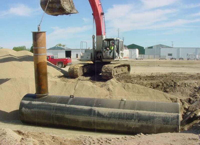
Picture 1 – Setting Tank on Bedding
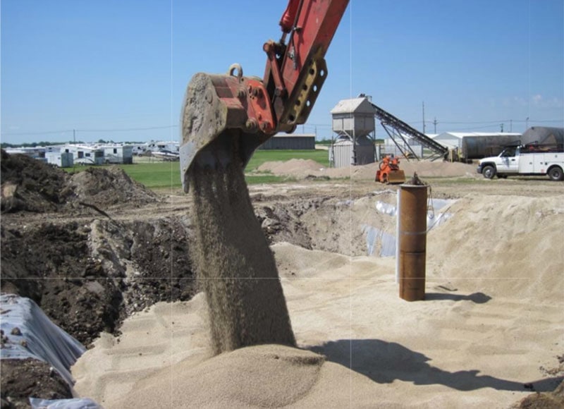
Picture 2 – Placing Backfill Over Tank
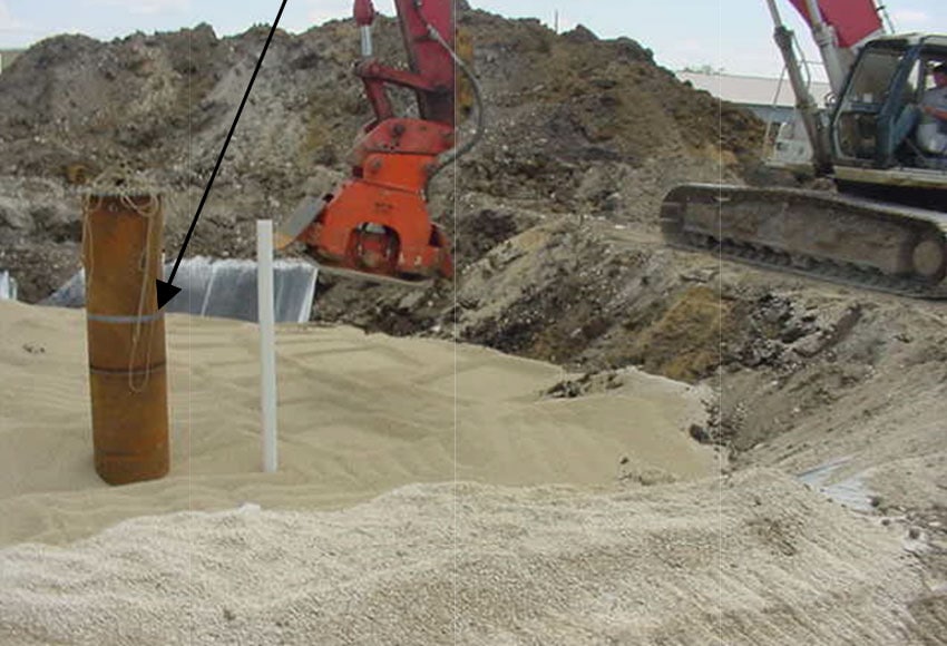
Picture 3 – Vibratory Plate Utilized for Backfill Consolidation
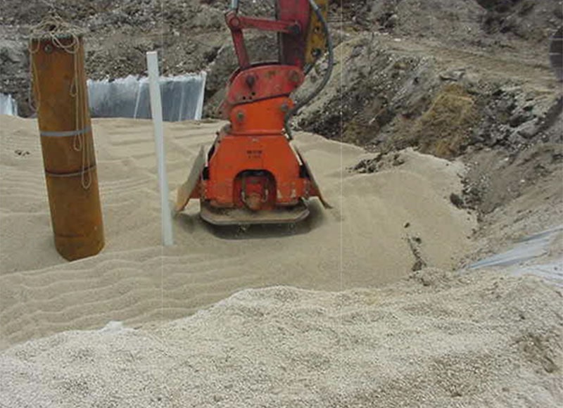
Picture 4 – Vibratory Plate Utilized for Backfill Consolidation
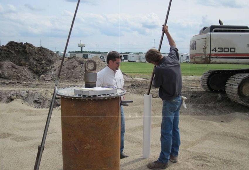
Picture 5 – Ground Water Level Verified
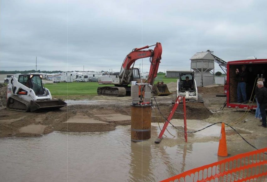
Picture 6 – Finished Backfill and Water at Ground Surface
At the completion of bedding and backfill, and prior to filling the pit with water, a man was lowered down the manhole and into the tank to measure the tank diameters to ensure the bedding and backfill operation had not impacted the roundness of the tank. Visual observation reported that the tank appeared to be round. Horizontal and vertical verification measurements were taken at the end of the tank near the flat plate head on the manhole end of the tank as well as in the middle of the tank and were recorded as follows:
Location 1, near tank head. Horizontal – 64-⅜ inches; Vertical – 64-⅜ inches
Location 2, at tank midpoint. Horizontal – 64-½ inches; Vertical – 64-½ inches
The pit was then flooded with water to the ground surface. This was done to model the previously mentioned requirements of UL 1316 Section 12, External Pressure Test, for FRP tank.
The test tank was left in this buried, submerged condition for 24 hours, again as required by Section 12. After 24 hours had elapsed, a video camera was mounted on the inside of the tank to provide live 360 degree view of the interior. Finally the entire assembly was closed up, air tight, in order to pull the required vacuum.
Vacuum Test
The vacuum test of the tank commenced on May 25, 2011. The initial goal was to meet the requirements of UL 1316 Section 12, meaning the tank would need to resist an internal vacuum pressure of 5.3 inches of mercury (Hg) as shown in Picture 7.
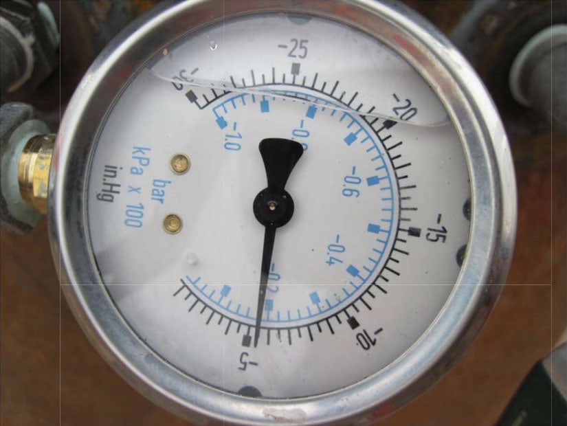
Picture 7 – Gage Reading at UL 1316 Test Requirement
After meeting the initial goal of the test, it was decided to keep pulling vacuum until a) the tank failed or b) maximum vacuum achievable with the pumps utilized was reached. Ultimately, after pulling vacuum for 4 hours, the vacuum pumps could not draw more than 16.5” Hg vacuum so the test was ended at that pressure. As expected, nothing happened during the test. The bedding soil held the tank in shape, preventing any type of buckling failure or collapse. While the vacuum was applied to the tank, video recording of the tank interior did not demonstrate any out- of-roundness of the tank or any buckling activity.
Discussion
The theoretical buckling resistance of the tank/soil backfill system can be approximated by the calculation procedure as shown in AWWA Manual M11, “Steel Water Pipe: A Guide for Design and Installation”, Fourth Edition (2004), Chapter 6, Page 63, Equation 6-7. This steel pipe buckling calculation procedure has had an excellent history of use in regards to buried steel pipe. In fact, it was based on work first published by the FRP pipe committee. As the design, manufacture and materials of steel tanks and steel pipe is similar, this time tested calculation procedure was utilized. Because of the quality of the soil support around the tank, it was predicted and expected that no buckling failure of the tank would occur. AWWA M11 equation 6-7:
![]()
qa is the allowable buckling load for the tank/soil backfill system, Rw is the water buoyancy factor, B’ is an empirical coefficient of elastic support, E’ is the modulus of soil reaction, EI is the tank wall stiffness, and D is the tank diameter. Using this equation that accounts for the quality of the support and backfill, the system strength, qa was calculated as 21.1 psi; while the total buckling load, which includes the internal vacuum of 16.5 inches of Hg, was only 15 psi, hence the optimism for a successful test. After completion of the test, the tank was exhumed the next day as shown in Pictures 8 and 9.
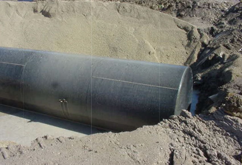
Picture 8 – Exhumed Tank After Test
Picture 9 – Tank Head Deflection
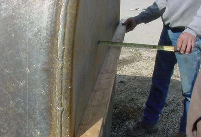
The authors were not present for this uncovering. However, the following items were noted by the Acterra Group personnel conducting the uncovering of the tank:
- Tank finally floated with less than 1 foot of backfill, but had about 6 feet of water over
- Both heads were deflected inward about 2 inches to 75 inches; see Picture 9 above.
- Visible creases on the head from the outside to the center of the head around the
- Shell of tank was unscathed
The real time video did not show evidence of the tank heads deflecting inward but after uncovering the tank, it was easy to measure this deflection (as shown in Picture 9). However, this could be expected as a flat plate surface would not have the same capacity (in either internal pressure or external load) as a curved surface. In addition, the bedding and backfill would not assist in the prevention of this deflection.
Conclusion
This test clearly demonstrates the benefits of utilizing the STI/SPFA tank installation instructions when burying an UST. The backfill material, properly placed, clearly assists in supporting the tank shell against damaging buckling loads. AWWA Manual M11 appears to be an appropriate design guide for predicting allowable buckling resistance of the tank/soil system as well as for calculation of the total buckling load.
If inward deflection of the flat plate test head is deemed undesirable, there are two alternate actions:
- Calculate the thickness required to limit the deflection of the head to a value of no more than D/360 or utilize stiffeners in conjunction with the typical head thicknesses if
- Utilize a dished head instead of a flat Calculate thickness required per the ASME Boiler & Pressure Vessel Code, Section VIII, Division 1.
Steel tanks and FRP tanks do have one similarity; they would both be considered flexible underground structures, that is, they both utilize the surrounding soil to assist in the resistance to external loads, including external radial fluid pressure. As such, it is appropriate for steel UST’s to utilize the bedding and backfill much the same as FRP UST’s presently do for support and resistance of buckling loads.
References
- American Iron & Steel Institute in cooperation with Steel Plate Fabricators Association (Division of STI/SPFA) (2007 Edition), Welded Steel Pipe Design Manual.
- American Society of Mechanical Engineers (2010), ASME Boiler & Pressure Vessel Code, Section VIII, Division 1.
- AWWA Manual M 11 (2004), Steel Water Pipe: A Guide for Design and Installation, Fourth Edition.
- Steel Tank Institute (Division of STI/SPFA), STI R971 (2011), ACT-100U Installation Instructions for Urethane Coated Underground Steel Storage Tanks.
- Underwriters Laboratories Standard UL 1316 (1996), Glass-Fiber-Reinforced Plastic Underground Storage Tanks for Petroleum Products, Alcohols, and Alcohol-Gasoline
- Underwriters Laboratories Standard UL 58 (1998), Steel Underground Tanks for Flammable and Combustible Liquids.
Published Date
October 1, 2012
Resource Type
- Research
Topic
- Underground
