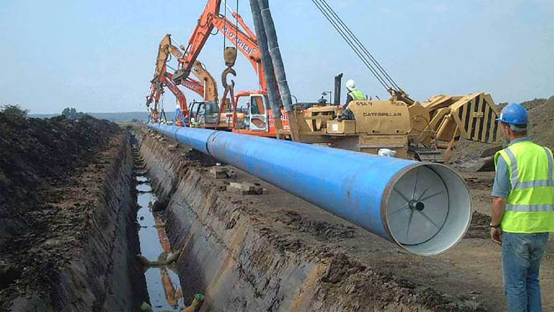
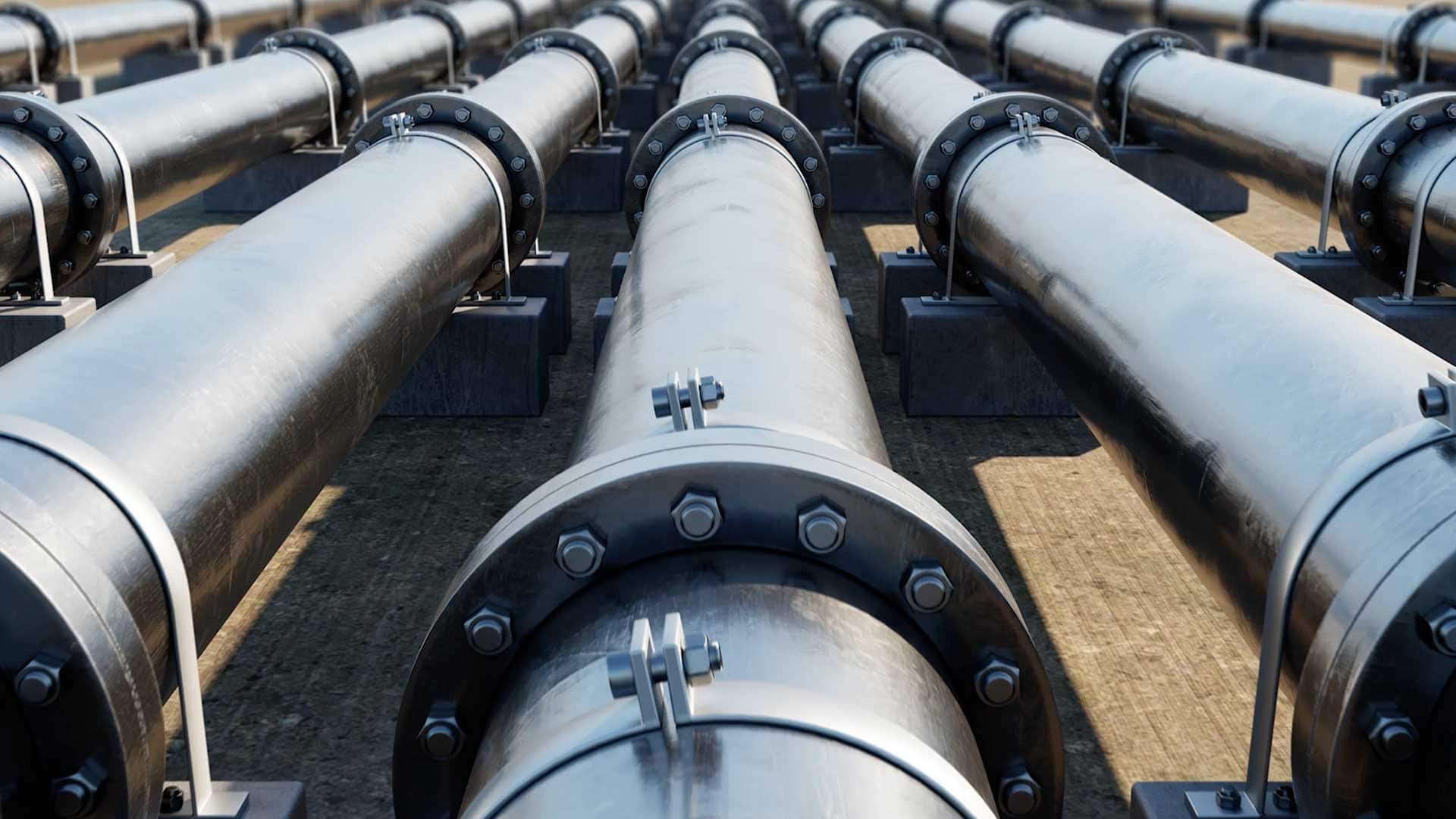
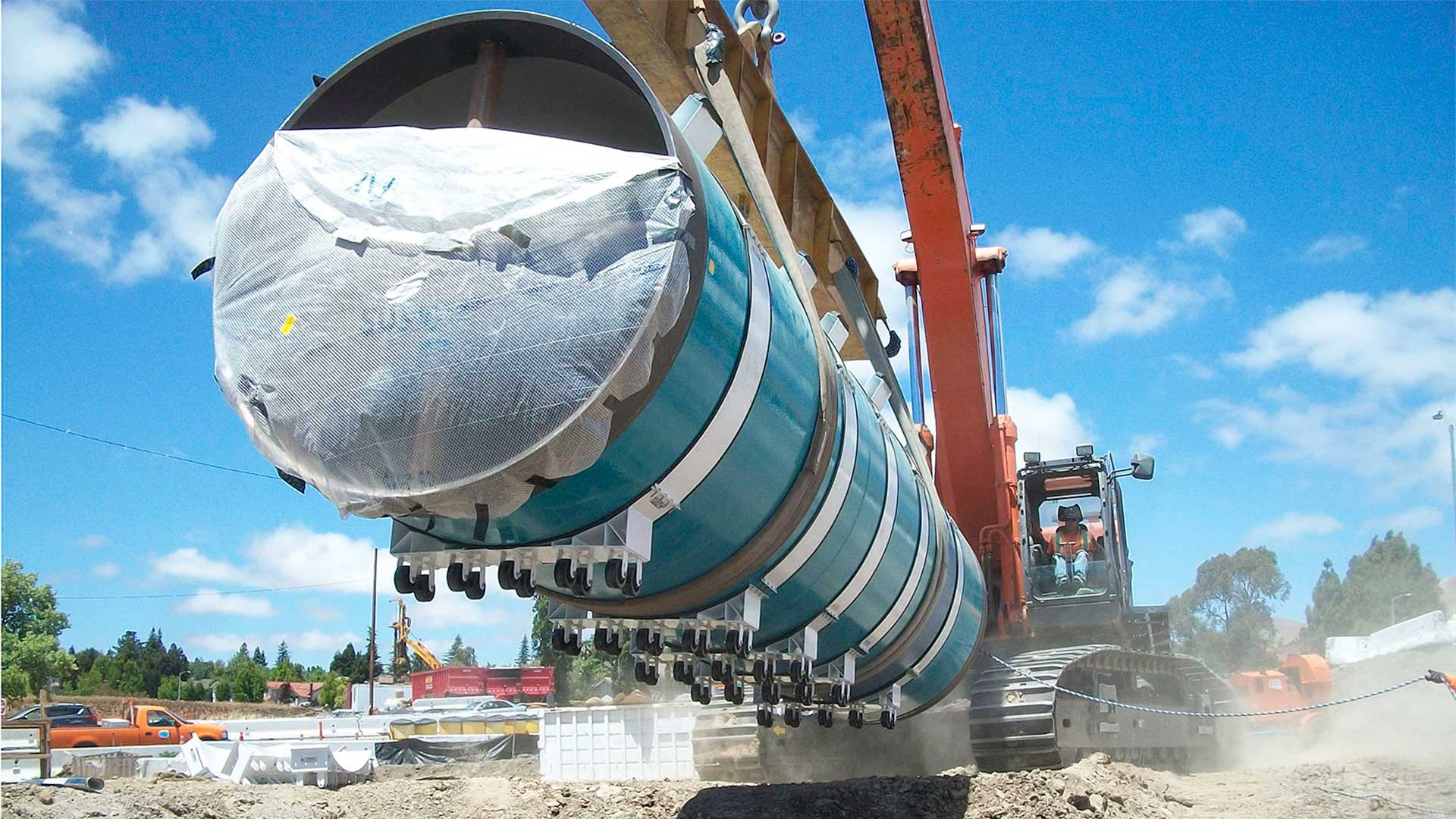
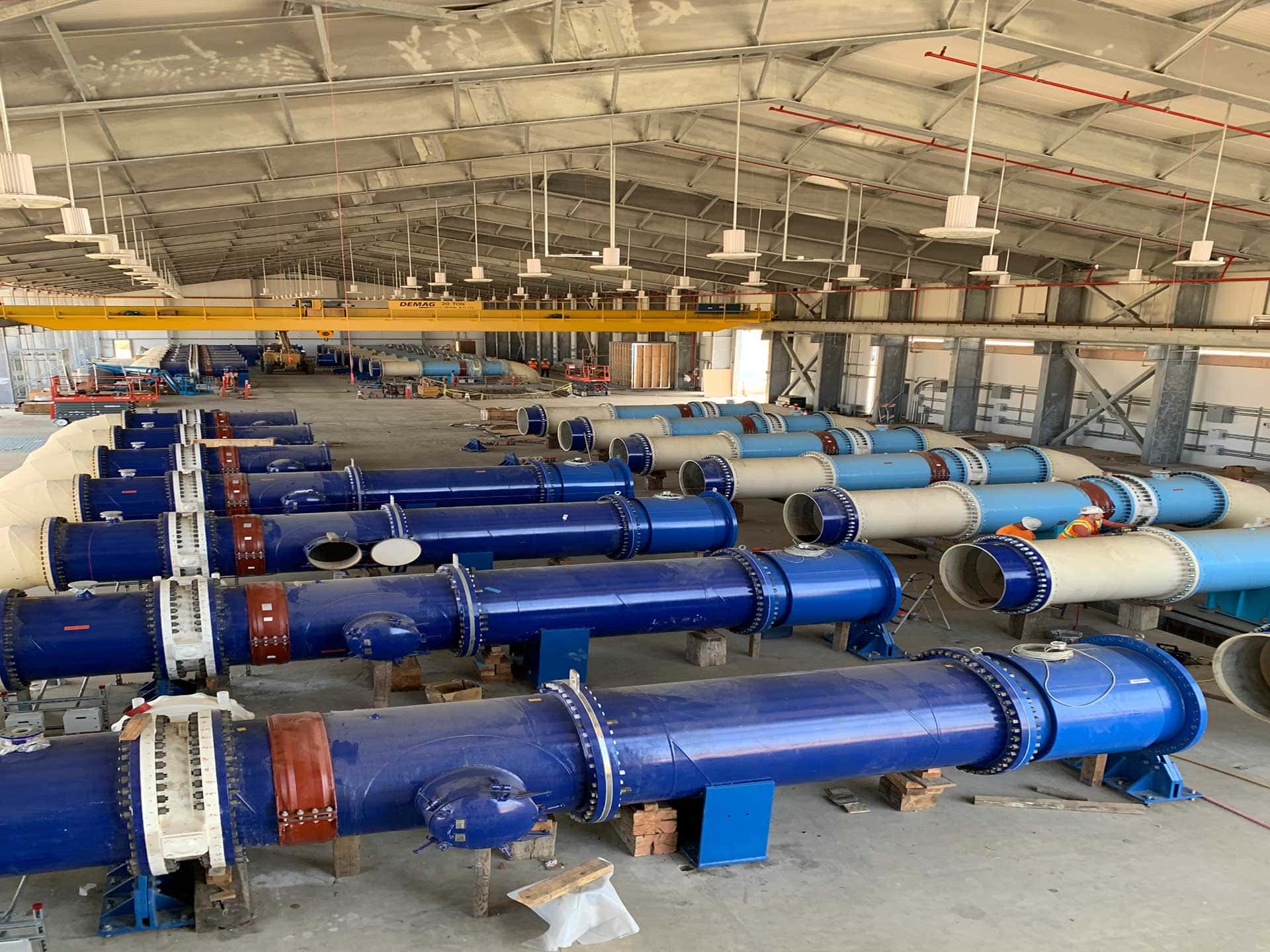
The 5th Edition of AWWA M11 has been out since 2017 and the benefits to engineers have been recognized for the additional value it has created for steel pipe design. There were numerous changes and additions that are intended to clarify important criteria and procedures when designing steel water pipe.
The nature of engineering design is that the knowledge used to design large facilities is learned and remembered mostly during the work on a project. This series of articles will highlight many of the major changes in the new AWWA M11.
One of STI/SPFA’s goals with our expert’s design tips is to point out important changes in the new edition of AWWA M11 and to provide background of why such revisions were made. Steel pipe systems have been designed, fabricated, and installed with decades of experience, achieving reliable and long-lasting operational service, while establishing proven safety factors that the engineering community has trusted. Steel pipe manufactured to AWWA standards are usually considered an engineered product and require a certain amount of engineering input to be functional for a water facility. This article will review buried pipe deflection and corresponding safety factors. It will also include “Good Engineering Practice” procedures as described in Article #4.
Buried Steel Pipe Deflection Design
In the early 1900’s Anson Marston was concerned with roads and how water would make them impassable during the rainy season. He decided to “get Iowa out of the mud.” Marston loads for rigid pipe, modified by M. G. Spangler for flexible pipe, and the Iowa formula were developed to predict how much load a flexible steel culvert could take without collapsing. From observations of existing culverts, it was determined steel culverts could withstand greater than 20% deflection before they would collapse. Spangler decided that a good safety factor would be 4:1 and he therefore used 5% as a safe deflection criterion for his Iowa deflection formula. After developing the formula, Spangler ran into problem making the formula work properly. Finally, one of his graduate students, Reynold Watkins, solved the problem and the Modified Iowa Formula was the result. It has been used in its original form since first developed in 1958 and has proven to be relatively accurate and conservative. The basic formula to predict steel pipe deflection as listed in AWWA M11 5th edition is shown below.
Where:
Δx = predicted horizontal deflection, in.
Dl = Deflection lag factor – normally taken as 1.0, unitless
K = Bedding constant – normal takes as 0.1, unitless
W = load per unit of length of pipe, lbs./linear in.
r = mean radius of the lined and coated pipe, in.
E’ = modulus of soil reaction of the embedment material, psi
EI = pipe wall stiffness, lb in = ESIS + ECIL + ECIC, in.-lbs.
ECIL + ECIC are used if the pipe is lined and/or coated with cement mortar. The terms represent the stiffness of the cement mortar lining and or cement mortar coating.
In basic terminology the formula is simply
Predicted Deflection = Load/ (Pipe Stiffness + Soil Stiffness)
Good Engineering and The Deflection Formula
There are many variables in a buried pipe installation. They are reflected in the above deflection formula. The remainder of the paper will define the terms in the formula. Some are well defined and others require engineering decisions based on the conditions the pipe will be laid in. We will also point out where good engineering practice can help make the engineering decisions easier and more cost effective.
Horizontal Deflection: The term Δx is the predicted horizontal deflection in inches. AWWA M11 recommends limiting this to 2% deflection for cement mortar coated pipe, 3% deflection for cement lined and flexible coated pipe and 5% for flexible lined and coated pipe.
A buried steel ring is stable up to a uniform elliptical deflection of approximately 20%. A 4 to 1 safety factor was chosen for a few main reasons. The original work by Spangler used a 4 to 1 safety factor to compensate for the variances in type of soil and compaction of the soil. A 5% value is also used as a reasonable limit for many buckling formulae. Many of the joints used on steel pipe are limited by approximately 5%.
Cement mortar lined pipe will withstand deflection up 6 to 10% without detrimental cracking to the lining. Cement mortar coating will withstand deflections up to 3 to 4% without detrimental cracking.
It must be understood that these deflections of 2% for cement coated pipe and 3% for cement lined pipe are limits to control cracking in the cement mortar and are not a limit on the structural strength of the pipe. The variances on shape of the elliptical deflection and strength of the cement mortar above the minimal allowable will affect the amount of cracking in the lining or coating. If a measurement slightly above the recommended value is measured then it is often prudent to examine the cement mortar lining or cement mortar coating (if possible) to ascertain the amount of cracking if any that has occurred. To reject the installation and have the pipe reburied is often a much worse solution than accepting slightly over deflected pipe with no sign of cracking of the cement mortar lining or cement mortar coating.
Load on pipe W = Wc and Wl :
Wc is the prism load on the pipe. Simply stated, the prism of load is the weight of the column of backfill directly over the top of the pipe without considering soil friction on the trench sidewalls or arching effects and is therefore the maximum load that can be imposed by the backfill on the flexible pipe over time. The formula for the prism load is:
Where:
Wc = prism load = dead load on the conduit, lbs./linear ft. of pipe
w = unit weight of fill, lbs./cu. ft.
Hc = height of fill above the top of pipe, ft.
Bc = outside diameter of coating on the pipe, in.
Wl is the live load where applicable. The live load is usually an HS-20 Highway loading and can obtained from M11 Table 5-1 which is based on ASTM A796. When obtained from Table 5-1, the units are in lbs./sq. ft. and are neglected if it is less than 100 lb./sq. ft. (See table at the end of this article.)
W as used in the deflection formula is the combined dead load and the live load. The units on the live load are in lbs./linear in. To get to the load in the correct units of lbs./linear in. the conversion is:
Deflection Lag Factor: This term accounts for long term settlement as a result of consolidation or settlement of the backfill material at the sides of the pipe. The original work Marston performed was in the mud on Iowa’s roads. In AWWA M11 the load is calculated as the prism of earth above the pipe. This is the maximum dead load the pipe should see over time. Because steel pipe is designed for maximum possible soil load directly over the outside of the diameter of the pipe when the prism load W is used, Dl is 1.0. The prism load is a conservative design approach, as the actual earth load on a flexible pipe lies somewhere between the Marston/Spangler trench load and the more conservative prism load. The soil load over time may approach the prism load due to the consolidation of the soils. But will not exceed it.
K: This term is the bedding constant and is usually taken 0.1
EI: EI = pipe wall stiffness, lb in = ESIS + ECIL + ECIC
ESIS represents the stiffness of the steel ring. ECIL + ECIC are used if the pipe is lined and/or coated with cement mortar. The terms represent the stiffness of the cement mortar lining and or cement mortar coating. E is the modulus of elasticity for each particular material. For steel the modulus of elasticity is 30,000,000 psi. For cement mortar lining and cement mortar coating the modulus of elasticity is 4,000,000 psi.
I is the transverse moment of inertia per unit length of pipe wall components. IS is for steel cylinder and IL and IC are for the cement mortar lining and cement mortar coating respectfully. I is calculated as I = t3/12. This is the only place in the formula where wall thickness occurs. The individual laminated rings act together and are additive for the complete stiffness of the pipe.
E’: This term is the modulus of soil reaction of the embedment material in psi. It represents a measure of the soil stiffness of the embedment around the pipe. It has been empirically derived and has been verified through numerous measurements of actual installations. The value of E’ varies with type of embedment material, compaction of the embedment material in the pipe zone and depth of cover. (See Table at the end of article for values of E’ from AWWA M11) The values shown in the table have proven to be conservative. There have been many discussions about the effect of the native soils outside of the excavated trench width. Dr. Watkins, the originator and developer of the Modified Iowa formula, found that E’ isn’t just based on the soil properties but was a function of the soil times the pipe radius, a hybrid property. Furthermore, Dr. Watkins has long stated that a trench width of 2 times the diameter of the pipe is the maximum width of the trench for pipe installed in very poor native soils. The effect of the pipe on the embedment soil is spread out in the shape of a trapezoid and makes insignificant effect on the native soil at that trench width.
Good Engineering Practice: The formula is relatively straight forward and easy to calculate. A Good Engineered pipeline is based on how the many variables are evaluated and input for the final design.
The first step in design is to find the required wall thickness of steel for internal working or operating pressure, surge pressure, test pressure, and handling. Once that is completed, then the minimum steel thickness for your pipeline is determined. The thickness “t” for the steel cylinder only occurs once in the deflection formula and usually has a relatively minor effect on the stiffness of the pipe and much lesser of an effect on the overall stiffness of the pipe and soil system. It is therefore good engineering practice to look at designing the soil envelope to control deflection. The choice of soil and compaction usually have a much larger effect on controlling the deflection than any other factors in the design of steel pipe. The choice of soil will vary with location. There is usually a type of soil that is available near the jobsite which can be used and yield a good E’ value. The cost of additional compactive effort can be obtained from a reliable contractor. An evaluation of the cost of increasing the steel thickness versus the cost of a better soil vs the amount of compaction is a relatively straight forward economic evaluation. In cases where the depth of cover is over 15 feet the, option of using soil cement, CLSM or enhanced soil often is a good economic solution. It gives you a great E’, the soil requires no compactive effort, and in most cases the trench width can be narrower.


Related Articles
- The 5th Edition of AWWA M11 Pipe Design Clarified #1 – Outlets: The Rest of the Story
- The 5th Edition of AWWA M11 Pipe Design Clarified #2 – Couplings, Bracing, and Anchor Rings
- The 5th Edition of AWWA M11 Pipe Design Clarified #3 – Torque Calculations
- The 5th Edition of AWWA M11 Pipe Design Clarified #4 – Good Engineering Practice
- The 5th Edition of AWWA M11 Pipe Design Clarified #5 – Steel Pipe: A Guide for Design and Installation
Featured Affiliate
Phoenix Forging Company, a member of the Phoenix Forge Group, is a proud domestic manufacturer of steel tank and cylinder fittings based in Catasauqua, PA. Phoenix Forge was founded in 1882.
www.phoenixforge.com“SPFA has helped not just us but the steel water pipe industry as a whole by having such a high standard of Quality Assurance Auditing.”
Nik Parsons
Mid America Pipe Fabricating & Supply, LLC