Part 1 – General
1.01 Description
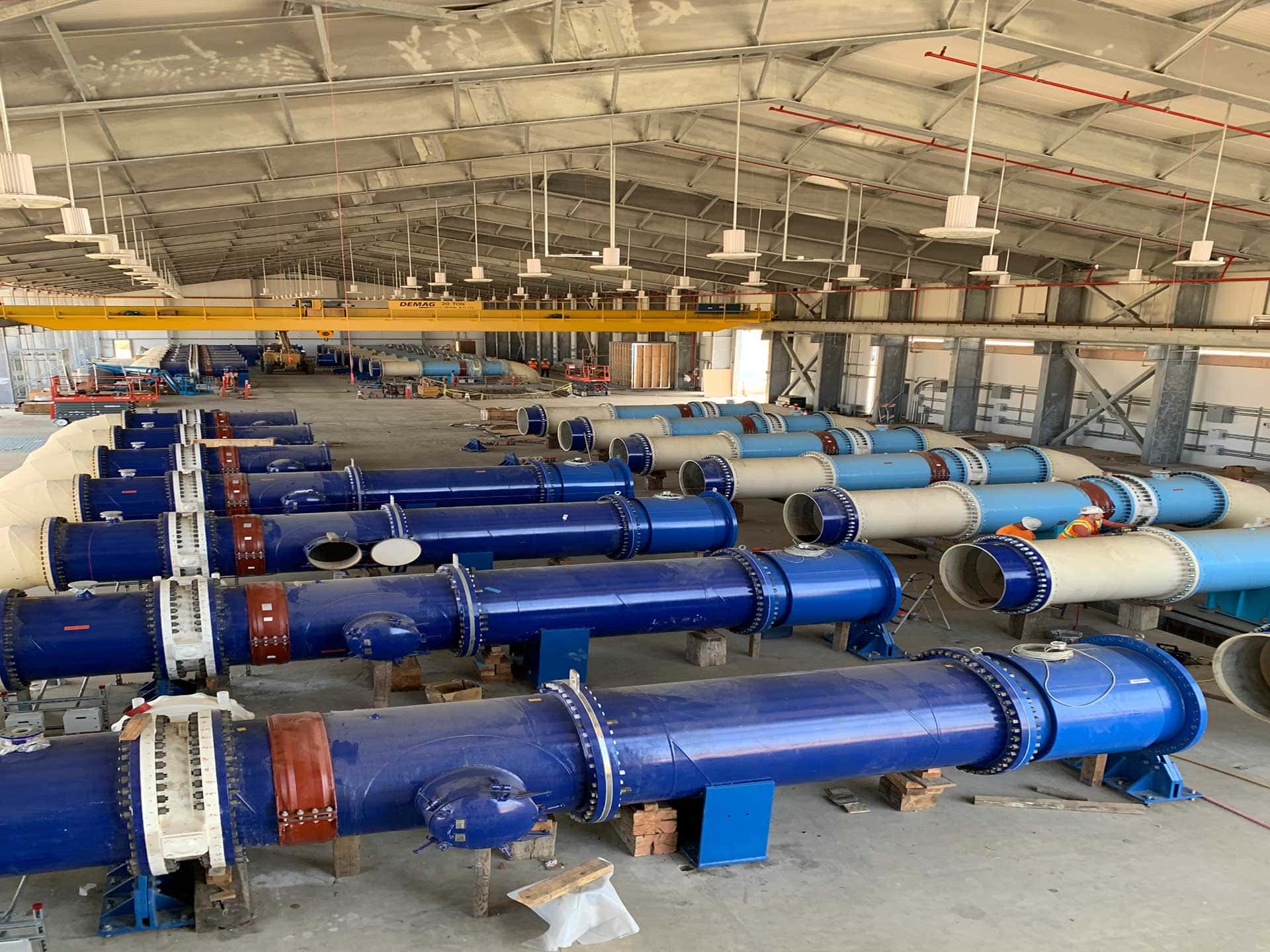
Scope of Work: Provide and install buried steel pipe of the sizes and in the locations shown on the drawings and as specified herein.
1.02 Quality Assurance
- Standards, latest edition (as applicable):
- AWWA C200 Steel Water Pipe 6 inches (150 mm) and Larger
- AWWA C205 Cement-Mortar Protective Lining and Coating for Steel Water Pipe – 4 Inches (100 mm) and Larger – Shop Applied
- AWWA C206 Field Welding of Steel Water Pipe
- AWWA C207 Steel Pipe Flanges for Waterworks Service, Sizes 4 In. Through 144 In. (100 mm Through 3,600 mm)
- AWWA C208 Dimensions for Fabricated Steel Water Pipe Fittings
- AWWA C209 Cold-Applied Tape Coatings for Steel Water Pipe and Fittings
- AWWA C210 Liquid-Epoxy Coatings and Linings for Steel Water Pipe and Fittings
- AWWA C214 Tape Coating Systems for Steel Water Pipe
- AWWA C216 Heat-Shrinkable Cross-Linked Polyolefin Coatings for Steel Water Pipe and Fittings
- AWWA C219 Bolted Sleeve-Type Couplings for Plain-End Pipe
- AWWA C222 Polyurethane Coatings and Linings for Steel Water Pipe and Fittings
- AWWA C227 Bolted, Split-Sleeve Couplings for Plain-End Pipe
- AWWA C604 Installation of Steel Water Pipe – 4 In. (100 mm) and Larger
- AWWA M11 Steel Pipe-A Guide for Design and Installation
- Qualifications:
- All steel pipe and fittings shall be furnished by manufacturers who are fully experienced, reputable, and qualified in the manufacture of the materials to be furnished. In addition, the plant in which the pipe or fittings is manufactured shall be SPFA certified. The pipe and fittings shall be designed, constructed and installed in accordance with the best practices and methods and shall comply with the Specifications as applicable.
1.03 Submittals
Prior to the start of manufacturing, the following shall be submitted to, and approved by the engineer:
- Shop Drawings, including pipe laying schedule and/or layouts. The schedule or layouts shall show each piece by mark number, with station and invert elevation at each pipe end.
- Details of specials and fittings.
- Calculations for pipe design and fittings reinforcement and/or test data as applicable.
- Copy of the manufacturer’s quality control check of pipe material and production.
- Upon completion of the manufacturing, the following shall be submitted to the engineer:
- An affidavit of compliance with AWWA standards referenced in this specification.
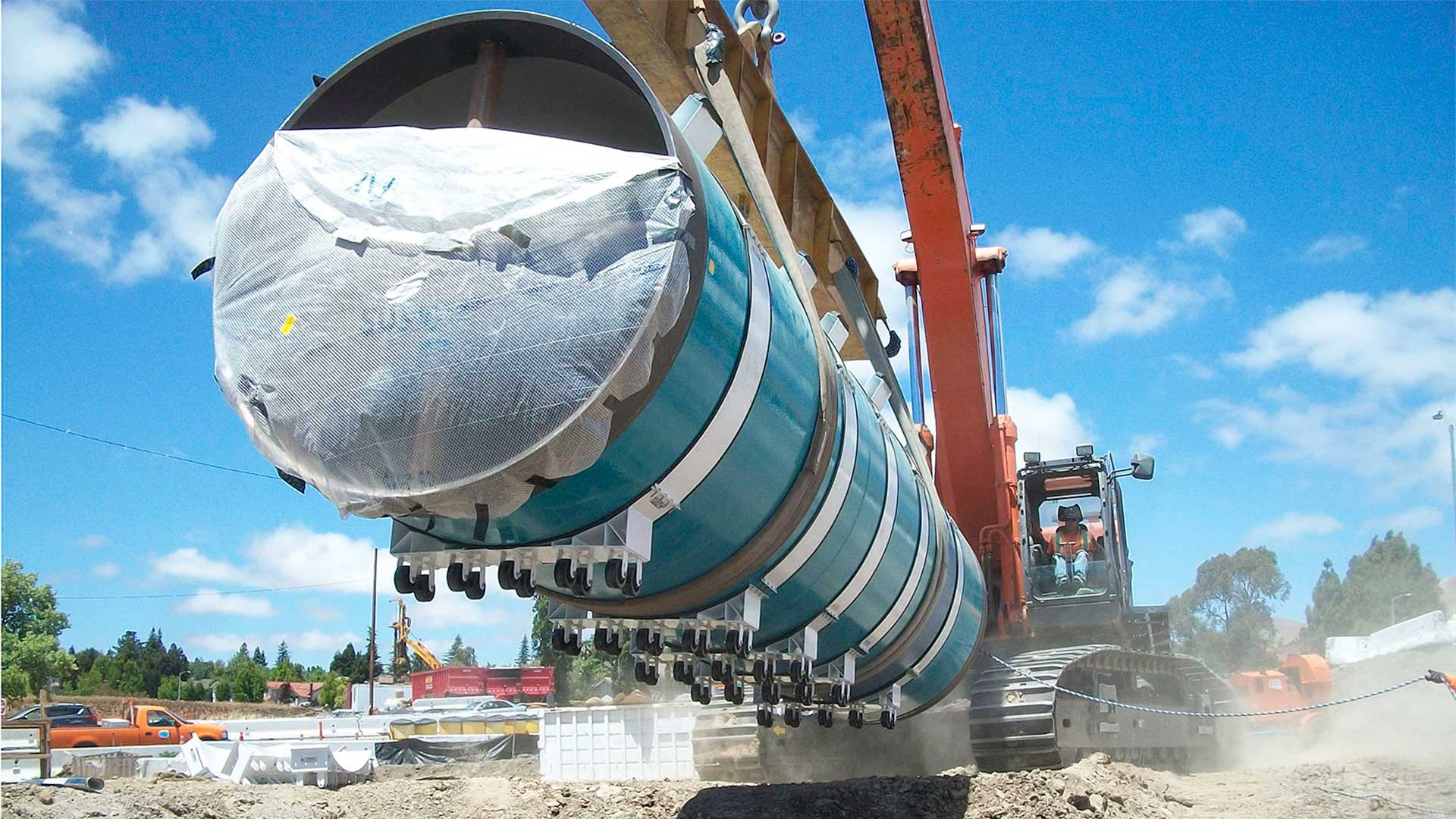
1.04 Handling, Storage and Shipping
- Pipe shall be braced as required in the latest edition of AWWA M11 to maintain roundness during shipping and handling.
- Coated pipe shall be shipped on bunks and secured with nylon belt tied down straps or padded banding located approximately over braces.
- Coated pipe shall be stored on padded skids, sand, or dirt berms, sandbags, rubber tires or other suitable means so that coating will not be damaged.
- Coated pipe shall be handled with the wide belt slings, padded forks, or other means that will not damage the pipe. Chains, cables or other equipment likely to cause damage to the pipe or coating shall not be used.
- Prior to shipment, the pipe shall be visually inspected for damage with particular attention given to the lining and coating. Any damaged areas shall be repaired in accordance with the standard to which the lining or coating was applied.
Part 2 – Products
2.01 Materials
- Pipe:
- Steel pipe shall be manufactured in accordance with the requirements of AWWA C200. Steel used for manufacturing of pipe cylinders shall be one of the steels and grades listed in AWWA C200.
- Standard pipe laying lengths shall be a minimum of 40 feet with special lengths, field trim pieces and closure pieces as required by plan and profile for location of elbows, tees, reducers and other in-line fittings.
- Interior Linings
- Pipe shall be cement-mortar lined in the shop by the centrifugal process in accordance with AWWA C205. Cement-mortar lined pipe shall have ends capped prior to shipment. For pipe 14-inch nominal diameter and larger, the finished ID after lining shall be equal to the nominal pipe size. For pipe 12-inch nominal diameter and smaller, standard pipe sizes per ANSI B36.10 shall be furnished.
- Fittings shall be cement-mortar lined in accordance with the applicable requirements in AWWA C205.
- (Use for Polyurethane lined pipe) Pipe shall be lined with polyurethane in accordance with AWWA C222. Lining thickness shall be a minimum of 20 mils.
- (Use for Epoxy lined pipe) Pipe shall be lined with epoxy in accordance AWWA C210. Lining thickness shall be a minimum of 16 mils.
- Pipe shall be cement-mortar lined in the shop by the centrifugal process in accordance with AWWA C205. Cement-mortar lined pipe shall have ends capped prior to shipment. For pipe 14-inch nominal diameter and larger, the finished ID after lining shall be equal to the nominal pipe size. For pipe 12-inch nominal diameter and smaller, standard pipe sizes per ANSI B36.10 shall be furnished.
- Exterior Coatings (unless otherwise specifically noted on the drawings):
- (Use for Polyurethane coated pipe) Pipe shall be coated with polyurethane in accordance with AWWA C222. Coating thickness shall be a minimum of 25 mils.
- (Use for tape coated pipe) Pipe shall be primed and coated with prefabricated multi-layer cold-applied polyethylene tape coatings in accordance with AWWA C214. The tape system shall be a total thickness of 50 mils for pipe diameters 54 inches and less and 80 mils for pipe diameters over 54 inches. Specials shall be primed and coated in accordance with AWWA C209 for a coating thickness of 30 mils minimum.
- (Use for mortar coated pipe) Pipe shall be coated with cement mortar in accordance with AWWA C205. Coating thickness shall be a minimum of ¾ inch.
- (Use for epoxy coated pipe) Pipe shall be coated with epoxy in accordance with AWWA C210. Coating thickness shall be a minimum of 16 mils.
- Concrete encased piping shall be furnished bare.
- Fittings:
- Fittings shall be fabricated in accordance with AWWA C200 Section 4 from pipe conforming to the above standards. Fittings fabricated from previously hydrostatically tested straight pipe shall require testing of only those welded seams that were not previously hydrostatically tested in the straight pipe. This testing shall be by the dye penetrant examination per ASTM E165 or magnetic particle examination in accordance with ASTM E709. Acceptance criteria shall be in accordance with ASME B&PV Code, Section VIII, Division 1, Appendix 8 for dye penetrant examination, and Appendix 6 for magnetic particle examination.
- Fittings shall conform to the dimensions of AWWA C208 or may be fabricated into standard or special pipe lengths. Elbows up to 22 ½ degrees shall be two- piece; over 22 ½ degrees through 45 degrees shall be three-piece; over 45 degrees through 67 ½ degrees shall be four-pieces; and over 67 ½ degrees through 90 degrees shall be five-pieces. Elbows shall have a minimum radius of 2 ½ times the nominal diameter, if site conditions permit. If the elbow radius is less than 2 ½ times the nominal diameter, the wall thickness must be calculated by the method provided in AWWA M11. All tees, laterals and outlets shall be reinforced in accordance with AWWA M11.
- Joints (Unless otherwise specifically noted on the drawings):
- Welded Lap Joints: Field welded lap joints shall be used where restrained joints are indicated on the plans and for all pipe sizes over 72-inch diameter or working pressures greater than 250 psi.The bell shall provide for a nominal lap such that the minimum engagement, with 1-inch allowable pull, is at least 1 inch or three times the thickness of the bell, whichever is greater. Shop applied lining and coating shall be held back sufficiently to allow for welding of the joint, except that cement-mortar lining may be continuous to the end of the spigot for pipe diameters 24 inches and smaller.
- Gasketed Joints: The standard joint for working pressures up to 250 psi (72-inch maximum nominal diameter) shall be rubber gasketed unless otherwise noted on the plans. Gasketed joints shall conform to AWWA C200 Standard and be either the Carnegie or rolled groove type. Rolled groove gasketed joints shall consist of a flared bell end formed and sized by the use of a segmental expander or by forcing the pipe end over a plug die. The spigot end groove, designed to retain the rubber gasket, shall be formed and sized by rolling on male-female dies to match the bell.
The gasket shall have sufficient volume to approximately fill the area of the groove and shall conform to AWWA C200.The joint shall be suitable for the pressures of the class of pipe on which it is furnished, and shall operate satisfactorily with a deflection, the tangent of which is not to exceed 0.75 inch/D where D is the outside diameter of the pipe in inches, or with a uniform pull-out of ¾ inch.
Rubber gasketed joints may be furnished only by a manufacturer who has furnished pipe with joints of similar design for comparable working pressure, pipe diameter, and wall thickness.
Shop applied coating shall be continuous to the end of the pipe on the bell end and shall be held back on the spigot end sufficiently to allow full engagement of the joint. Shop applied lining shall be continuous to the end of the pipe on the spigot
end and shall be held back on the bell end beyond the point of maximum engagement as recommended by the manufacturer. For gasketed joints, the exposed surfaces of the bell and spigot shall be painted with one shop coat of a holding primer.
- Couplings: Couplings where indicated on the plans shall be bolted sleeve-type conforming to AWWA C 219, or bolted, split-sleeve style conforming to AWWA C 227. Couplings shall be restrained as required by the specifications or as shown in AWWA M11.Couplings for buried service shall have all metal parts coated with epoxy paint conforming to AWWA C210 or powder coated conforming to AWWA C213.
Pipe for use with couplings shall have ends prepared to meet the requirements of the AWWA coupling standard. Buried pipe with couplings must have the pipe ends held round for most couplings to perform properly. Consult with the coupling manufacturer for pipe end tolerances and out-of-roundness limitations for both installing the couplings and for in service performance of the couplings.
- Flanges:
- Flanges shall be in accordance with AWWA C207 Class D for working pressures to 175 psi on 4-inch through 12-inch diameter, and 150 psi on diameters over 12 inches.
- Flanges shall be AWWA C207 Class E for working pressures over 150 psi to 275 psi when mating steel to steel.
- Flanges shall be AWWA C207 Class F for working pressures to 300 psi (drilling to match ANSI B16.5 Class 250).
- Shop lining and coating shall be continuous to ends of pipe and backs of flanges. Coatings shall not interfere with the proper installation of the bolts and/or nuts.
- Gaskets: Gaskets shall be furnished in accordance with AWWA C207.
- Bolts and nuts for flanges located indoors and in enclosed vaults and structures shall be carbon steel, in accordance with AWWA C207.
2.02 Design
- Pipe Design
- Steel pipe shall be designed in accordance with AWWA M11.
- Pipe shall be designed for a working pressure of (to be supplied by engineer) psi and a maximum pressure (test or transient) of 1.5 times the working pressure unless otherwise shown on the plans.
- Pipe shall be designed for internal pressure using the hoop stress formula:t=pd/2s
Where:
t = nominal pipe wall thickness for the specified internal design pressure, in.
p = internal design pressure, psi
d = outside diameter of steel pipe cylinder (not including coatings), in.
s = allowable design stress, psi. Allowable design stress shall be 50% of steel yield strength for working pressure and 75% of steel yield strength for surge or test pressure, psi
- Buried Pipe Deflection Design
- The predicted earth load on the pipe shall be calculated using the prism of earth method as described in AWWA M11 which is shown below:Wc = wHe(Dc/12)
Where:
Wc = Prism Load = dead load on the conduit. Lb/lin ft. of pipe
w = unit weight of fill – lbs per cu ft
Hc = height of fill above top of pipe ft
Dc = outside diameter of coated pipe. In - Live loads (Wl) shall be HS20 Highway loads. Lb/ft2
- Predicted deflection shall be calculated using the Modified Iowa formula from AWWA M11 and as shown below:Δx = Dl[(KWr3)/(EI + 0.061E’r3)]
Where:
Δx = predicted horizontal deflection of pipe, in
Dl = 1.0 (deflection lag factor)
K = 0.1 (bedding constant)
W = load per unit of pipe length = [Wc/12 + WlDc/144]
r = mean radius of pipe
E = modulus of elasticity, 30,000,000 psi for steel (Es) and 4,000,000 psi for cement-mortar (Iy & Ic)
I = transverse moment of inertia per unit length of individual pipe wall components (for steel cylinder (IS), for cement-mortar lining (IL), and for cement-mortar coating (IC)
= t3/12, in.3
E’ = Modulus of soil reaction = 1000 psi**Note to specifier – E’ varies with type of soil, compaction, and depth of cover. 1,000 psi represents a coarse-grained soil compacted to 90% standard proctor density at 2 to 5 ft of cover. For more values see AWWA Manual M11-5th Edition Table 5-3. It is almost always more economical to enhance the stiffness of the soil with compaction or utilize better soils if deflection controls the design of the wall thickness. E’ can be increased from 1,000 psi to 1,600 psi by increasing compaction from 90% to 95% standard proctor density. Values of E’ of 3,000 psi to 10,000 psi can be achieved by using soil cement (CLSM).
- Allowable deflection shall be calculated (or field measured) to be 3% or less for steel pipe with cement-mortar lining and flexible coating, and 2% for steel pipe with cement-mortar lining and cement-mortar coating.
- The predicted earth load on the pipe shall be calculated using the prism of earth method as described in AWWA M11 which is shown below:Wc = wHe(Dc/12)
- Handling
- The minimum wall thickness for handling of cement mortar lined steel pipe shall be a ratio of Diameter divided by wall thickness (D/t) of 240.
Part 3 – Execution
3.01 Inspection and Testing
- All pipe shall be inspected and tested at the manufacturing facility per the applicable AWWA standards and this specification.
- The Owner shall have the right to have any or all piping, fittings or specials inspected and tested by an independent testing agency at the manufacturing facility or elsewhere. Such inspection and testing will be at the Owner’s expense.
- Mark as rejected and immediately remove from the jobsite, or repair to the Owner’s satisfaction, all pipe lengths exhibiting signs of damage to the lining, coating, joints, or pipe wall.
3.02 Installation
- The Contractor shall provide and install all required piping and accessories in accordance with the Contract Documents and manufacturer’s recommendations. Pipe installation as specified in this section supplements AWWA C604.
- Joint assembly
- Gasketed joints:
- Install the gasket, assemble and test the joint in accordance with AWWA C604.
- Electrically bond joints as required and as shown on the plans and specifications.
- (Use for tape, epoxy, or polyurethane coated pipe) Coat the joint exterior by application of either a heat shrinkable sleeve conforming to AWWA C216, or cold applied tape conforming to AWWA C209. The applied thickness of the heat shrinkable sleeve shall be 60 mil minimum, or as recommended by the sleeve manufacturer, whichever is greater. The cold applied tape shall consist of primer, and 30 mil tape with 50% overlap for a total thickness of 60 mils.
- (Use for mortar coated pipe) Coat the joint exterior by placing a heavy-duty diaper over the joint. The diaper shall be wide enough to span the entire uncoated area of the joint except for an opening at the top for the placement of the grout. The diaper shall be secured by steel strapping. Grout shall be 1-part Type V cement and 2 parts sand mixed with water to the consistency of thick cream. Grout shall be poured in one side of the diaper only. Using a rod, proceed until the entire joint recess is filled. See AWWA C205 for additional coating procedures.
- Coat the joint interior by mortaring the annular space with a stiff mix of non-shrink grout. The finished joint shall be smooth and flush with the adjacent interior pipe surface.
- Lap field welded joints:
- Wire brush exposed end of joint surfaces.
- Insert the plain end into the expanded bell such that the minimum overlap at any location around the joint circumference is in accordance with AWWA C206 and this specification.
- A single full thickness fillet weld shall be provided by welders qualified as required by AWS D1.1. The weld can be on either the inside of the pipe or the outside of the pipe, at the option of the welder. Where installed in casing pipe, or otherwise noted on the plans, joints shall be provided with a full fillet weld on one side and a seal weld on the opposite side to allow an air test of the joint through a threaded outlet provided by the pipe manufacturer. Air-test the joint in accordance with AWWA C206. The threaded outlet shall be plugged by welding or other suitable methods following a successful air test.
- Field weld procedures shall be qualified in accordance with AWS D1.1.
- Complete linings and coatings as specified by the applicable AWWA standard.
- Flanged joints:
- Assemble flanged joints in accordance with AWWA C604.
- Execute care when tightening joints to prevent undue strain upon valves, pumps and other equipment.
- If flanges leak under pressure testing, loosen, or remove the nuts and bolts, reset or replace the gasket, reinstall or retighten the bolts and nuts, and retest the joints. Joints shall be watertight.
- Mechanical joints and couplings:
- Mechanical joints and couplings shall be installed in accordance with the manufacturer’s recommendations.
- Gasketed joints:
- Installing Buried Piping:
- Inspect each pipe and fitting before lowering the buried pipe or fittings into the trench. Inspect the interior and exterior protective coatings. Patch damaged areas in the field per the applicable AWWA standard and the coating manufacturer’s recommendations to the satisfaction of the Engineer. Clean ends of pipe thoroughly. Remove foreign matter and dirt from inside of pipe and keep clean during and after installation.
- Handle pipe in a manner to avoid any damage to the pipe. Do not drop or dump pipe into trenches under any circumstances.
- When installing piping in trenches, do not deviate more than one inch from line or grade. Measure for grade at the pipe invert.
- Grade the bottom of the trench and place a 4-inch minimum layer of bedding material under the pipe. Before installing each section of the pipe, check the grade with a straight edge and correct any irregularities found. The trench bottom shall form a continuous and uniform bearing and support for the pipe at every point between bell holes, except that the grade may be disturbed for the removal of lifting tackle.
- At the location of each joint, dig bell (joint) holes in the bottom of the trench and at the sides of dimensions to permit visual inspection of the entire joint and welding if required.
- Keep the trench in a dewatered condition during pipe installation.
- When the pipe installation is not in progress, close the open ends of pipe. DO NOT permit trench water, animals, or foreign material to enter the pipe.
- Field Hydrostatic Testing: Test in accordance with AWWA C604. Field test pressure shall be no more than 125% of the working or operating pressure at the lowest point of the section being tested. Allowable leakage shall be as shown in AWWA C604. Any visible leakage shall be stopped, even if within the C604 allowance.